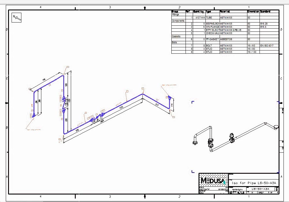
For most of my career I have hand drawn all piping isometric drawings affiliated with my projects. I have almost 30 years experience as a pipe fitter, job planner, and pipe designer. To answer your question directly: drafting in AutoCAD for piping iso's offers not much of an advantage due to the nature of simplicity piping iso's are. But this calls for an entirely different approach to a project altogether. The only time this changes is when you have a specialty software that can model an entire piping system in 3D during a design phase of the project, then produce automatic isometrics in which a pipe fitting team would order material and begin fabrication from. Iso's in AutoCAD are honestly the same thing as a sketch on an isopad. A CAD drafting program can be set up to produce very quick iso's once you have done it enough times but the time it takes would be the same I would imagine.

Hand sketched iso's is very fast and simple once you have the the info and not sure a CAD application can beat the time and effort for simple iso's to hand off to a pipe fitter. Is this truly the program I need or is there another AutoCad type program geared specifically for pipe drawings that have a library of piping and valve components? Thanks ! Since I've always used 30/60 isometric paper and draw to scale it's very quick to whip out a pencil and straight rule and pop out a drawing. But I'm finding at the moment I can still hand draw an iso quicker than I can do one with AutoCad Mechanical. Without much experience with AutoCad I still thought this was going to be the cure all alternative to countless hours of hand drawing isometric pipe drawings. Recently my employer gave me access to AutoCad Mechanical 2017.


I have almost 30 years experience as a pipe fitter, job planner, and pipe designer.


 0 kommentar(er)
